Learning Outcomes
By the end of this session the student should be able to identify and understand the components involved in serial communication. The terms that the student will be able to identify and understand include:
RS232, UART, modem & null modem, and USB.Readings: Fitzgerald
Appendix B - pages 432 ff
Chapter 4 - pages 107 ff
Questions - page 130 nos 1 to 30
Introduction
When we look at serial communications we are concentrating on the communication
between devices wher information is transfered as a continuos stream of bits along a pair
of wires. The IBM PC has always had the facility to perform serial communication using one
or both of the serial communications ports that are standard on most PCs.
When discussing serial communications we commonly refer to PCs as DTE (data terminating equipment) devices and we refer to the equipment that allows communication to occur as DCE (data communicating equipement) devices. Common forms of DCE are PCs, dumb terminals, and facsimilie machines, while the most common form of DCE is the modem.
The diagram shows an interface cable connecting to a PC to a modem, the connecter to which the cable attaches is referred to as a DB25 connector. The DB25 connector is component of a standard which defines how serial communications devices are connected called the RS232 standard. The RS232 standard also defines a smaller connector called a DB9, which uses less wires to perform a similar function to the DB25.
RS232
In the early 1960s, a standards committee, today known as the Electronic
Industries Association, developed a common interface standard for data communications
equipment. At that time, data communications was thought to mean digital data exchange
between a centrally located mainframe computer and a remote computer terminal, or possibly
between two terminals without a computer involved. These devices were linked by telephone
voice lines, and consequently required a modem at each end for signal translation. While
simple in concept, the many opportunities for data error that occur when transmitting data
through an analog channel require a relatively complex design. It was thought that a
standard was needed first to ensure reliable communication, and second to enable the
interconnection of equipment produced by different manufacturers, thereby fostering the
benefits of mass production and competition. From these ideas, the RS232 standard was
born. It specified signal voltages, signal timing, signal function, a protocol for
information exchange, and mechanical connectors.
Over the 30+ years since this standard was developed, the Electronic Industries
Association published three modifications, the most recent being the EIA232E standard
introduced in 1991. Besides changing the name from RS232 to EIA232, some signal lines were
renamed and various new ones were defined, including a shield conductor.
During this 30-year-long, rapidly evolving period in electronics, manufacturers adopted simplified versions of this interface for applications that were impossible to envision in the 1960s. Today, virtually all contemporary serial interfaces are EIA232-like in their signal voltages, protocols, and connectors, whether or not a modem is involved. Because no single "simplified" standard was agreed upon, however, many slightly different protocols and cables were created that obligingly mate with any EIA232 connector, but are incompatible with each other. Most of the difficulties you will encounter in EIA232 interfacing include at least one of the following:
- The absence or misconnection of flow control (handshaking) signals, resulting in buffer overflow or communications lock-up.
- Incorrect communications function (DTE versus DCE) for the cable in use, resulting in the reversal of the Transmit and Receive data lines as well as one or more handshaking lines.
- Incorrect connector gender or pin configuration, preventing cable connectors from mating properly.
Fortunately, EIA232 driver circuitry is highly tolerant of misconnections, and will usually survive a drive signal being connected to ground, or two drive signals connected to each other. In any case, if the serial interface between two devices is not operating correctly, disconnect the cable joining this equipment until the problem is isolated.
The diagram below shows the full EIA232 signal definition for the DTE device (usually the PC). The most commonly used signals are shown in bold.

Signal ground and shield.
Pin 7, Pin 1, and the shell are included in this category.
Cables provide separate paths for each, but internal wiring often connects pin 1 and the
cable shell/shield to signal ground on pin 7.
Pin 7 - Ground All signals are referenced to a
common ground, as defined by the voltage on pin 7. This conductor may or may not be
connected to protective ground inside the DCE device. The existence of a defined ground
potential within the cable makes the EIA232 standard different from a balanced
differential voltage standard, such as EIA530, which provides far greater noise immunity.
Primary communications channel.
This is used for data interchange, and includes flow control signals.
Pin 2 - Transmitted Data (TxD) This signal is active when data is
transmitted from the DTE device to the DCE device. When no data is transmitted, the signal
is held in the mark condition (logic '1', negative voltage).
NOTE: Pin 2 on the DCE device is commonly labeled "Received Data",
although by the EIA232 standard it should still be called Transmitted Data because the
data is thought to be destined for a remote DTE device.
Pin 3 - Received Data (RxD) This signal is
active when the DTE device receives data from the DCE device. When no data is transmitted,
the signal is held in the mark condition (logic '1', negative voltage).
NOTE: Pin 3 on the DCE device is commonly labeled "Transmitted Data",
although by the EIA232 standard it should still be called Received Data because the data
is thought to arrive from a remote DTE device.
Pin 4 - Request to Send (RTS) This signal is
asserted (logic '0', positive voltage) to prepare the DCE device for accepting transmitted
data from the DTE device. Such preparation might include enabling the receive circuits, or
setting up the channel direction in half-duplex applications. When the DCE is ready, it
acknowledges by asserting Clear to Send.
NOTE: Pin 4 on the DCE device is commonly labeled "Clear to Send",
although by the EIA232 standard it should still be called Request to Send because the
request is thought to be destined for a remote DTE device.
Pin 5 - Clear to Send (CTS) This signal is
asserted (logic '0', positive voltage) by the DCE device to inform the DTE device that
transmission may begin. RTS and CTS are commonly used as handshaking signals to moderate
the flow of data into the DCE device.
NOTE: Pin 5 on the DCE device is commonly labeled "Request to Send",
although by the EIA232 standard it should still be called Clear to Send because the signal
is thought to originate from a remote DTE device.
Transmitter and receiver timing signals.
If a synchronous protocol is used, these signals provide timing information for the
transmitter and receiver, which may operate at different baud rates.
Pin 15 - Transmitter Signal Element Timing (TC) (also called Transmitter Clock)
This signal is relevant only when the DCE device is a modem and is operating with a
synchronous protocol. The modem generates this clock signal to control exactly the rate at
which data is sent on Transmitted Data (pin 2) from the DTE device to the DCE device. The
logic '1' to logic '0' (negative voltage to positive voltage) transition on this line
causes a corresponding transition to the next data element on the Transmitted Data line.
The modem generates this signal continuously, except when it is performing internal
diagnostic functions.
Pin 17 - Receiver Signal Element Timing (RC) (also
called Receiver Clock) This signal is similar to TC described above, except that
it provides timing information for the DTE receiver.
Pin 24 - Transmitter Signal Element Timing (ETC) (also
called External Transmitter Clock) Timing signals are provided by the DTE device
for use by a modem. This signal is used only when TC and RC (pins 15 and 17) are not in
use. The logic '1' to logic '0' transition (negative voltage to positive voltage)
indicates the time-center of the data element. Timing signals will be provided whenever
the DTE is turned on, regardless of other signal conditions.
Channel test signals.
Before data is exchanged, the channel may be tested for its integrity, and the baud rate
automatically adjusted to the maximum rate that the channel can support.
Pin 18 - Local Loopback (LL) This signal
is generated by the DTE device and is used to place the modem into a test state. When
Local Loopback is asserted (logic '0', positive voltage), the modem redirects its
modulated output signal, which is normally fed into the telephone line, back into its
receive circuitry. This enables data generated by the DTE to be echoed back through the
local modem to check the condition of the modem circuitry. The modem asserts its Test Mode
signal on Pin 25 to acknowledge that it has been placed in local loopback condition.
Pin 21 - Remote Loopback (RL) This signal is
generated by the DTE device and is used to place the remote modem into a test state. When
Remote Loopback is asserted (logic '0', positive voltage), the remote modem redirects its
received data back to its transmitted data input, thereby remodulating the received data
and returning it to its source. When the DTE initiates such a test, transmitted data is
passed through the local modem, the telephone line, the remote modem, and back, to
exercise the channel and confirm its integrity. The remote modem signals the local modem
to assert Test Mode on pin 25 when the remote loopback test is underway.
Pin 25 - Test Mode (TM) This signal is relevant
only when the DCE device is a modem. When asserted (logic '0', positive voltage), it
indicates that the modem is in a Local Loopback or Remote Loopback condition. Other
internal self-test conditions may also cause Test Mode to be asserted, and depend on the
modem and the network to which it is attached.
A modem allows a PC to connect to other computers and enables it to send and receive files of data over the telephone network. At one end it converts digital data into a series of analogue signals for transmission over telephone lines, at the other it does the opposite, converting an analogue signal into digital data.
Modems come in two types, internal, fitting into an expansion slot inside the PC’s system case or external, connected to the PC via one of its serial ports (COM1 or COM2).
Early modems were asynchronous devices, operating at slow rates of up to 18000 bit/s in FSK modulation, using two frequencies for transmission and another two for receiving. Asynchronous data is not accompanied by any clock, and the transmitting and receiving modems know only the nominal data rate. To prevent slipping of the data relative to the modems' clocks, this data is always grouped in very short blocks (characters) with framing bits (start and stop bits). The most common code used for this is the seven-bit ASCII code with even parity.
Synchronous modems operate at rates up to 56 Kbit/s in audio lines, using synchronous data. Synchronous data is accompanied by a clock signal and is almost always grouped in blocks. It is the responsibility of the data source to assemble those blocks with framing codes and any extra bits needed for error detecting and/or correcting according to one of many different protocols (BISYNC, SDLC, HDLC, etc.). The data source and destination expect the modem to be transparent to this type of data, conversely, the modem can ignore the blocking of the data. The usual modulation methods are the phase modulation and integrated phase and amplitude.
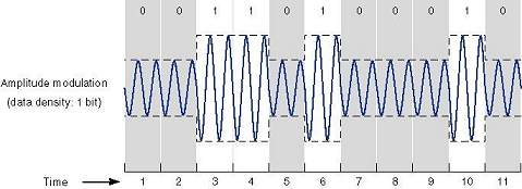
ModulationData communication means moving digital information from one place to another through communication channels. These digital information signals have the shape of square waves and the meaning of '0' and '1'.
If such digital signals were transmitted on analogue media the square waves of the digital signals would be distorted by the analogue media. The receiver which receives these distorted signals will be unable to interpret accurately the incoming signals. The solution is to convert these digital signals into analogue signals so that the communication channels can carry the information from one place to another reliably. The technique which enables this conversion is called 'modulation'.
Modulation is a technique of modifying some basic analogue signal in a known way in order to encode information in that basic signal. Any measurable property of an analogue signal can be used to transmit information by changing this property in some known manner and then detecting those changes at the receiver end. The signal that is modulated is called the carrier signal, because it carries the digital information from one end of the communication channel to the other end.
The device that changes the signal at the transmitting end of the communication channel is called the 'modulator'. The device at the receiving end of the channel, which detects the digital information from the modulated signal, is called the 'demodulator'.
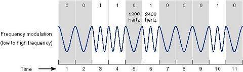
With Frequency Modulation, the frequency of the carrier signal is changed according to the data. The transmitter sends different frequencies for a '1' than for a '0'. This technique is also called FSK - frequency shift keying. Its disadvantages are that the rate of frequency changes is limited by the bandwidth of the line, and that distortion caused by the lines makes the detection even harder than amplitude modulation. Today this technique is used in low rate asynchronous modems up to 1200 baud only.
The Amplitude Modulation (AM) technique changes the amplitude of the sine wave. In the earliest modems, digital signals were converted to analogue by transmitting a large amplitude sine wave for a '1' and zero amplitude for a '0'. The main advantage of this technique is that it is easy to produce such signals and also to detect them. However, the technique has two major disadvantages. The first is that the speed of the changing amplitude is limited by the bandwidth of the line. The second is that the small amplitude changes suffer from unreliable detection. Telephone lines limit amplitude changes to some 3000 changes per second. The disadvantages of amplitude modulation causes this technique to no longer be used by modems, however, it is used in conjunction with other techniques.
Phase Modulation (PM) is a process where two sinusoidal waveforms are compared with each other. The case where the two waveforms are going in the same direction at the same time is known as zero phase shift. With a phase shift of 180 degrees, waveform B starts at the mid-point of waveform A, so that when waveform A is positive waveform B is negative, and vice versa. Two phase states allow the representation of a single bit of digital data, which can have the value '0' or '1'. Additional 90- and 270 degree phase shifts provide four phase shift states and the capability to represent four digital data representations.

This technique, in order to detect the phase of each symbol, requires phase synchronisation between the receiver's and transmitter's phase. This complicates the receiver's design.
A sub method of the phase modulation is 'differential phase modulation'. In this method, the modem shifts the phase of each succeeding signal in a certain number of degrees for a '0' (90 degrees for example) and a different certain number of degrees for a '1' (270 degrees for example ). This method is easier to detect than the previous one. The receiver has to detect the phase shifts between symbols and not the absolute phase. This technique is also called 'phase shift keying' (PSK). In the case of two possible phase shifts the modulation will be called BPSK - binary PSK. In the case of 4 different phase shifts possibilities for each symbol which means that each symbol represents 2 bits the modulation will be called QPSK, and in case of 8 different phase shifts the modulation technique will be called 8PSK.
Quadrature Amplitude Modulation (QAM) allows the transmission of data using both the phase shift of PM and the signal magnitude of AM at the same time. The more phase shifts and magnitude levels used, the more data the technique can be used to transmit. However, multibit technology eventually runs out of steam. As the number of tones and phases increases, the more difficult it becomes to differentiate between similar combinations.
The PSTN was designed for voice communications - by artificially limiting the sound spectrum to just those frequencies relevant to human speech, network engineers found they could reduce the bandwidth needed per call - and while this works well for voice, it imposes limits on data communications. According to Shannon's Law, the limitations of the PSTN impose a maximum theoretical data transmission limit of 35 Kbit/s for a wholly analogue-based connection.
SpeedThe first of many bottlenecks in the stream of data is at the UART (Universal Asynchronous Receiver/Transmitter), the chip which controls the connection between the serial port and the PC’s bus system. PCI bus systems operate in blocks of 32 bits, while serial cables transmit bits in single file. The UART has to take all the traffic coming at it full speed and funnel it down into the serial port without causing gridlock. The older INS 8250-B and INS 16450 UARTs cannot keep up with the transmission speeds modern modems are capable of. Only a newer 16550 UART guarantees communication at speeds of 28.8 Kbit/s without data loss.
The next obstacle to overcome is the telephone line itself. It is a mistake to think the phone system is all digital; many analogue elements remain. Not even all exchanges are digital. Lines into the home are typically still analogue and susceptible to all the problems associated with this medium. The main problem is limited bandwidth, which is the amount of information that can be fitted on a line. Another is line noise.
Various standards have been developed to overcome the problem of line noise. One modem sends signals to the other it wants to connect with, to see how that modem wants to communicate and to assess the condition of the line. The two modems then send messages back and forth, agreeing a common mode of operation in a process known as handshaking.
The speed at which the modem will communicate is effectively limited by the slowest component in the chain. If the phone connection is poor or full of line noise, the rates will drop until a reliable link can be maintained. A modem capable of 33.6 Kbit/s will have to drop to 14.4 Kbit/s if communicating with a 14.4 Kbit/s modem. The culmination of the handshaking process is an agreed standard which includes a common speed, an error correction format and a rate of compression.
The modem divides the data into packets, chopping it into easily digestible chunks. It adds more data to the packet to mark where each one begins and ends. It adds parity bits or checksums to determine whether the data received in the packet is the same as that sent, and whether the decompression formula has been correctly applied. If a packet is incorrectly received, the receiving modem will need to ask the transmitting modem to resend it. There also needs to be confirmation on the amount of data being sent, so the connection is not dropped before the last of the data has got through, or kept waiting for non-existent data to be received.
The entire handshaking operation is controlled from within the modem. The connection can be dropped many times before it is finally established and the process can take as long as 30 seconds over analogue lines.
Note that there is a common misunderstanding of the reported connect speed message (for example, 'connected at 115200') that users see when they establish a dial-up network connection. This relates to the DTE (Data Terminal Equipment) speed, the speed of the connection between the PC and the modem, not to the speed at which the modems are communicating. The latter, known as the DCE (Data Communications Equipment) speed, is agreed during the handshaking procedure.
Serial portsIn an AT/ISA-bus machine, all serial data transfers are handled by the CPU and each byte must pass through the CPU registers to get to memory or disk. This means that access times must be fast enough to avoid read overrun errors and transmission latency at higher bit rates. In fact when the IBM PC-AT came out, the performance of the INS16450 was adequate because the speed at which data was routinely transmitted through the serial port was significantly less than is possible with modern modems.
To understand the limitations of the INS 16450, it is necessary to recognise how the serial port interrupts the CPU which has to finish its current task, or service a higher-priority interrupt, before servicing the UART. This delay is the bus latency time associated with servicing the UART interrupt request. If the CPU cannot service the UART before the next data byte is received (by the UART from the serial port), data will be lost, with consequent retransmissions and an inevitable impact on throughput.
This condition is known as overrun error. At low bit rates the AT system is fast enough to read each byte from the UART receiver before the next byte is received. The higher the bit rate at the serial port, the higher the strain on the system to transfer each byte from the UART before the next is received. Higher bit rates cause the CPU to spend increasing amounts of time servicing the UART, thus making the whole system run inefficiently.
To attack this problem, National Semiconductor developed the NS16550A UART. The 16550 overcomes the previous problems by including First In First Out (FIFO) buffers on the receiver and transmitter, which dramatically improve performance on modem transfer speeds of 9.6 Kbit/s or higher.
The size of the receiver FIFO ensures that as many as 16 bytes are ready to transfer when the CPU services the UART receiver interrupt. The receiver can request transfer at FIFO thresholds of one, four, eight, 16 bytes full. This allows software to modify the FIFO threshold according to its current task and ensures that the CPU doesn’t continually waste time switching context for only a couple of bytes of data received.
The transmitter FIFO ensures that as many as 16 bytes can be transferred when the CPU services the UART transmit interrupt. This reduces the time lost by the CPU in context switching. However, since a time lag in servicing an asynchronous transmitter usually has no penalty, CPU latency is of no concern when transmitting, although ultimate throughput may suffer.
StandardsV.22bis, V.32 and V.32bis were early standards specifying speeds of 2.4 Kbit/s, 9.6 Kbit/s and 14.4 Kbit/s respectively.
The V.34 standard was introduced towards the end of 1994, supporting 28.8 Kbit/s, and is now considered the minimum acceptable standard. V.34 modems are able to drop their speed to communicate with slower modems and interrogate the line, adjusting their speed up or down according to the prevailing line conditions.
In 1996 the V.34 standard was upgraded to V.34+, which allows for data transfer speeds of up to 33.6 Kbit/s, is backwards compatible with all previous standards, and adapts to line conditions to eke out the greatest usable amount of bandwidth.
The table below shows uncompressed data throughput rates for the various modem types. Data compression can increase throughput by a factor of 2 or 3. However, because graphic images on web pages are already compressed, the real multiplier for web browsing generally works out to around 1.5 to 2x the listed rates. Two figures are shown for V.90 modems because the wide variation in connect speeds.
| Standard | Date | Bit/s |
Bytes/s |
KB/min |
MB/hour |
MinSec/MB |
| V.32 | 1984 | 9,600 |
1200 |
70 |
4 | 14m 33s |
| V.32bis | 1991 | 14,400 |
1800 |
106 |
6 | 9m 42s |
| V.34 | 1994 | 28,800 |
3600 |
211 |
12 | 4m 51s |
| V.34+ | 1996 | 33,600 |
4200 |
246 |
14 | 4m 09s |
| V.90 |
1998 | 42,000 |
5250 |
308 |
18 22 |
3m 19s 2m 48s |
Other important V dot standards include V.17 which allows connection to Group III fax machines, which are ordinary standalone fax machines, V.42 which is a worldwide error correction standard designed to cope with garbled data caused by interference on phone lines, and V.42bis which is a data compression protocol.
The MNP (Microm Networking Protocol) standards go from MNP Class 1 to MNP Class 10. They do not stand alone, but operate in conjunction with other modem standards. MNP 1 is half-duplex. MNP Classes 2 to 4 deal with error control and can transmit data error-free by resending blocks of data that become corrupted in transmission. MNP Classes 5 to 10 address various modem operating parameters. MPN Class 5 is is an advanced data compression protocol which can compress data by a factor of two, effectively doubling the speed of data transfer. MNP Class 10 is Microcom's proprietary error-control protocol. It provides a set of ‘adverse channel enhancements’ which help modems cope with bad phone connections by making multiple attempts to make a connection, and adjust both the size of the data packets and the speed of the transfer according to the condition of the line. The most common MNP protocols are numbers 2 to 5, with 10 also often included.
LAPM (Link Access Protocol for Modems), one of the two protocols specified by V.42 used for detection and correction of errors on a communications link between two modems, has largely superseded MNP. V.42bis is an algorithm used by modems to compress data by a theoretical ratio of 8:1. In the real world, however, a ratio of 2.5:1 is typical. MNP 4 error correction and MNP 5 compression are used as fallbacks if a remote modem doesn't support LAPM or V.42bis.
The Hayes AT Command Set was developed by Hayes, the modem manufacturer, and is now a universal standard. Each command line must start with the two-character attention code AT (or at). The command set is simply a series of instructions for automatically dialling numbers, controlling the telephone connection and telling the computer what it is doing.
FTPs (file transfer protocols) were developed to help prevent errors when transferring files before standards were introduced. Zmodem is still widely used for file transfer over the serial port. If the received data doesn't match the information used to check the quality of data, the system notifies the sender that an error has occurred and asks for a retransmission. This is the protocol used to download a file to a computer from another computer on the Internet.
BABT (British Approvals Boards of Telecommunications) is an important standard, since modems that are not ‘BABT approved’ are not legal for use in Britain.
56 Kbit/s
1997 saw the arrival of the 56 Kbit/s modem, despite the absence of any international
standard for this speed. The K56Flex group of companies, including 3Com, Ascend, Hayes,
Motorola, Lucent and Rockwell, used Rockwell chipsets to achieve the faster speed, while
companies like US Robotics used its own x2 technology. The two systems were not
compatible, forcing users and Internet Service Providers (ISPs) to opt for one or the
other. Moreover, there are basic limitations to 56K technology. It uses asymmetric data
rates and thus can achieve high speeds only when downloading data from such as an
ISP’s server.
Most telephone exchanges, in this and almost every other country around the world are digital, and so are the connections between exchanges. All ISPs have digital lines linking them to the telephone network (in Europe, either E1 or ISDN lines). But the lines to most homes and offices are still analogue, which is a bugbear when it comes to data exchange: they have limited bandwidth and suffer from line noise (mostly static). They were designed to transfer telephone conversations rather than digital data, so even after compression there is only so much data that can be squeezed onto them. Thus the fatuity that digital data from a PC has to be converted to analogue (by a modem) and back to digital (by the phone company) before it hits the network.
56K makes the most of the much faster part of the connection - the digital lines. Data can be sent from the ISP over an entirely digital network until it reaches the final part of the journey from a local CO to the home or office. It then uses pulse code modulation (PCM) to overlay the analogue signal and squeeze as much as possible out of the analogue line side of the connection. However, there is a catch: 56K technology allows for one conversion from digital to analogue, so if, by chance, there is a section in the connection which runs over analogue and then returns to digital, it'll only be possible to connect at 33.6 Kbit/s (maximum).
The reason it's not possible to upload at 56K is simply because the analogue lines are not good enough. There are innumerable possible obstacles to prevent a clear signal getting through, such as in-house wiring anomalies, varying wiring distances (between 1-6Km) and splices. It is still theoretically possible to achieve a 33.6 Kbit/s data transfer rate upstream, and work is being carried out to perfect a standard that will increase this by a further 20 to 30%. Another problem created by sending a signal from an analogue line to a digital line is the quantisation noise produced by the analogue-to-digital (ADC) conversion.
The digital-to-analogue conversion (DAC) can be thought of as representing each eight bits, as one of 256 voltages - a translation done 8000 times a second. By sampling this signal at the same rate, the 56 Kbit/s modem can in theory pass 64 Kbit/s (8000x8) without loss. This simplified description omits other losses which limit the speed to 56 Kbit/s.
There is also some confusion as to the possible need to upgrade the PC serial port to cope with 56 Kbit/s operation. These days this usually uses the 16550 UART chip, itself once an upgrade to cope with faster modems. It is rated at 115 Kbit/s but 56 Kbit/s modems can overload it because they compress and decompress data on the fly. In normal Internet use data is mostly compressed before being sent, so compression by the modem is minimal.
On 4 February 1998 the ITU finally brought the year-long standards battle to an end by agreeing a 56 Kbit/s standard, known as V.90.
After months of deadlock the ITU finally agreed a 56 Kbit/s standard, known as V.90, in February of 1998. Though neither K56Flex nor x2, the V.90 standard uses techniques similar to both and the expectation was that manufacturers would be able to ship compliant product within weeks rather than months. The new standard was formally ratified in the summer of 1998, following a several month approval process.
V.90
The V.90 standard is neither x2 nor K56Flex, although it does use
techniques from both. It is actually two standards in one, the specification defining 'a
digital modem and analogue modem pair capable of transmitting data at up to 56 Kbit/s
downstream and up to 33.6 Kbit/s upstream'. In this case, downstream means from the
digital to the analogue modem. The former is connected to the PSTN via an ISDN line and
will usually be part of a bank of modems connected to a multiple-line ISDN at an ISP. The
analogue modem plugs into the PSTN at the subscriber's end.
The key to V.90's 56 Kbit/s capability is the PCM coding scheme introduced by the standard's proprietary forerunners. PCM codes are are digital representations of audio signals and are the telephone system's native language. The exchange generates these on receipt of analogue signals from the subscriber's handset. They're eight bits long and are transferred at a rate of 8,000 per second - a total throughput of 64 Kbit/s. A V.90 digital modem uses a large subset of these code to encode data and delivers them to the telephone system via an ISDN link. At the subscriber's end, the codes are converted to an analogue signal by the exchange - as if they had been created in the usual way - and these tones are sent to the subscriber's modem.
Most of the work in creating V.90 went into he line-probing and signal-generation schemes. When a V.90 connection is first established, the two modems send each other a list of their capabilities. If V.90 communication is possible, the analogue and digital modems send test signals to each other to check the quality of their connection and establish whether there are any digital impairments in the telephone system that might prevent the PCM codes from arriving correctly. For example, on some long distance or international calls, the 64 Kbit/s signal is compressed to 32 Kbit/s (or more) for reasons of economics - and this ruins V.90.
If there are no impairments, the analogue modem analyses the signals from the digital modem and informs it how best to encode its data. The two modems also sort out what the round-trip delay is and work out what equalisation to apply to the line to get the best possible frequency response.
Coding the information into PCM is a complex business. The telephone system doesn't treat PCM codes linearly. Instead, it allocates more PCM codes to lower signal levels and fewer codes to higher levels. This corresponds with the way the human ear responds to sound, but it also means that the receiving modem might not be able to distinguish between some of the adjacent codes accurately. Also, the signal synthesised by the digital modem must be able to be accurately converted to analogue and sent through the analogue parts of the telephone exchange.
Error connection and detection systems also limit the sequential permutations possible. In short, there are sequences of codes that can't be sent and others that must be sent, but these are dependent on the data being transmitted. A final complication is that the American and European telephone systems use different sets of PCM codes.
Initial reports indicate that V.90 provides higher speeds and more reliable connections than either of its two predecessors. The facts will be established during the several-month approval process due to be completed later in the summer of 1998, when the new standard is slated for formal ratification. Beyond that, the ITU has already set up a study group for the next generation of PCM modems, with the intention of achieving a 40 Kbit/s to 45 Kbit/s transmission speed from the analogue modem.
Fax modems
Nearly all modems now include some sort of fax capability and usually come with
bundled software which provides a PC with most of the functionality of a fax machine.
Digital documents can be converted to analogue, ending up as an image file (if the
receiver is another fax/modem), or a printed document (if received by a facsimile
machine). Incoming faxes received as image files are saved to the PC’s hard disk.
Fax-modems exploit the intelligence of the PC at their disposal to do things standalone fax machines can’t. For instance, faxes can be scheduled to be sent when the phone rates are cheaper. Also, since the data they receive is in digital form, it is immediately available on the PC for editing or retouching before printing. One of the common features in fax software is a cover-sheet facility which allows the definition of a fax cover-sheet. There’s often a quick-fax facility, too, which allows a single page fax to be created without the hassle of loading a word processor.
Group 3 fax/modems provide various levels of processing based upon their service class. Class 1 devices perform basic handshaking and data conversion and are the most flexible, because much of the work is done by the computer's CPU. Class 2 devices establish and end the call and perform error checking. There are a variety of de facto Class 2 implementations and one Class 2.0 standard. As PCs have become more powerful, future service classes with more features are unlikely.
One problem with scanned images and received faxes is that they hog large amounts of disk space. Some bundled fax software includes an optical character recognition facility (OCR) which allows received faxes or scanned images to be converted from bitmap format to normal text. This not only reduces document sizes but also allows them to be edited in a word processor.
Voice modems
Voice modems are part of the current communications convergence trend - the merging of
voice, data, fax, and even video - which is affecting all aspects of data communications.
Consider the Internet, originally a file transfer system, which is now transmitting radio
signals, real-time audio, telephone conversations and, for those who have the bandwidth,
live video. Now, a number of modem manufacturers have produced modems which can answer
phones and record voice messages.
Such multi-purpose modems perform as anything from a simple answering machine (recording messages on the hard disk) to a complete voicemail system with hundreds of boxes, message forwarding, and fax retrieval service. Incoming data or fax calls are automatically directed to the appropriate software module and voice calls passed through to the answering machine/voicemail software.
The Null Modem
Null modem cables allow transmission between two microcomputers
that are next to each other (six to eight feet apart) without using a modem. The cable is
called a null modem cable, because it eliminates the need for a pair of modems. To
transfer data between two microcomputers, hook up the null modem cable using the serial
ports, and use the communications software that would have been used to communicate via
modems, set one microcomputer in auto-answer mode and get the other to all it making sure
you skip the step of dialling. The null modem cable interconnects leads in such a way as
to fool both DTEs into thinking that they are connected to modems.
USB Bus
The USB bus, short for Universal Serial Bus, is a new external bus standard that
supports data transfer rates of 12 Mbps (12 million bits per second). A single USB port
can be used to connect up to 127 peripheral devices, such as mice, modems, and keyboards.
USB also supports Plug-and-Play installation and hot plugging.

Starting in 1996, a few computer manufacturers started including USB support in their new machines. Since the release of Intel's 440LX chipset in 1997, USB has become more widespread. It is expected to eventually completely replace serial and parallel ports.