Learning Outcomes
By the end of this session the student should be able to evaluate a selection of network configurations and apply planning and design issues to given situations. This session considers point-to-point, multiplex, multipoint, packet swtiching, message switching, Frame and Cell relay. Introduction Point-to-point circuits are
circuits that go from one point to another point. A point-to-point circuit means that an
organisation builds a private network and, in doing so, has a communication circuit going
from its host computer to a remote terminal. Point-to-point circuits are sometimes called
two-point circuits. This type of configuration is quite advantageous when the remote
terminal has enough transmission data to fill the entire capacity of the data circuit.
When an organisation builds a network using point-to-point circuits, many point-to-point
circuits may emanate from the front end processor ports to various terminals wherever they
are located. When you use a dial-up telephone network to make a telephone call, you are
creating a point to point connection.
Intelligent Terminal Controller
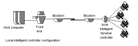 The diagram shows a network using
a local intelligent terminal controller at a remote point of a point-to-point circuit.
Local intelligent terminal controllers frequently control 16 terminals simultaneously. The
primary reason for employing this device are to load the point-to-point circuit more
efficiently and to serve as a security restrictor.
Multidrop (Return to sub-index)
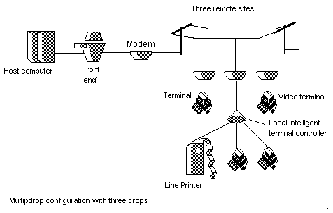 The diagram shows a multidrop
configuration. Organisations that design multidrop configurations do to load the
communication circuit more efficiently, reduce circuit mileage, and thus save money.
Mutiplex
 To mutiplex is to place two or
more signals on the communication circuit simultaneously. The primary benefit of
multiplexing is to save communication circuit costs between the host computer and many far
flung remote sites.
Switched Communication Networks
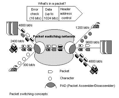 Packet switching is a store
and forward data transmission technique in which messages are split into small segments
called packets. A packet switching network is a special kind of wide area network.
Packet networks are referred to as X.25 networks., after the X.25 international
standard on which they are based. They are value added networks (VAN) because the common
carrier (Telecom) adds value by enhancing circuit features. When a message is sent from a
terminal in a packet switching network, the message is divided into equal-sized packets
and then transmitted through the network to the destination node. At the other end the
packets are reassembled into their original message and delivered to the appropriate
destination terminal. Packets belonging to different messages can travel via the same
communication circuits. Morever, the action we call switching moves the packets
from one circuit to another so that they can reach their respective destinations. A virtual
circuit is what connects the communicating terminals or microcomputers.
Virtual
Circuits
Packet switching is a store
and forward data transmission technique in which messages are split into small segments
called packets. A packet switching network is a special kind of wide area network.
Packet networks are referred to as X.25 networks., after the X.25 international
standard on which they are based. They are value added networks (VAN) because the common
carrier (Telecom) adds value by enhancing circuit features. When a message is sent from a
terminal in a packet switching network, the message is divided into equal-sized packets
and then transmitted through the network to the destination node. At the other end the
packets are reassembled into their original message and delivered to the appropriate
destination terminal. Packets belonging to different messages can travel via the same
communication circuits. Morever, the action we call switching moves the packets
from one circuit to another so that they can reach their respective destinations. A virtual
circuit is what connects the communicating terminals or microcomputers.
Virtual
CircuitsFrame Relay is an example of a packet-switched technology. Packet-switched networks enable end stations to dynamically share the network medium and the available bandwidth. Variable-length packets are used for more efficient and flexible transfers. These packets then are switched between the various network segments until the destination is reached. Statistical multiplexing techniques control network access in a packet-switched network. The advantage of this technique is that it accommodates more flexibility and more efficient use of bandwidth. Most of today's popular LANs, such as Ethernet and Token Ring, are packet-switched networks.
Frame Relay often is described as a streamlined version of X.25, offering fewer of the robust capabilities, such as windowing and retransmission of last data, that are offered in X.25. This is because Frame Relay typically operates over WAN facilities that offer more reliable connection services and a higher degree of reliability than the facilities available during the late 1970s and early 1980s that served as the common platforms for X.25 WANs. As mentioned earlier, Frame Relay is strictly a Layer 2 protocol suite, whereas X.25 provides services at Layer 3 (the network layer) as well. This enables Frame Relay to offer higher performance and greater transmission efficiency than X.25 and makes Frame Relay suitable for current WAN applications, such as LAN interconnection.
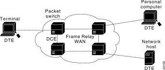
Devices attached to a Frame Relay WAN fall into two general categories: data terminal equipment (DTE) and data circuit-terminating equipment (DCE). DTEs generally are considered to be terminating equipment for a specific network and typically are located on the premises of a customer. In fact, they may be owned by the customer. Examples of DTE devices are terminals, personal computers, routers, and bridges.
DCEs are carrier-owned internetworking devices. The purpose of DCE equipment is to provide clocking and switching services in a network, which are the devices that actually transmit data through the WAN. In most cases, these are packet switches. The figure below shows the relationship between the two categories of devices.

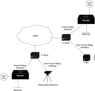
A common private Frame Relay network implementation is to equip a T1 multiplexer with both Frame Relay and non-Frame Relay interfaces. Frame Relay traffic is forwarded out the Frame Relay interface and onto the data network. Non-Frame Relay traffic is forwarded to the appropriate application or service, such as a private branch exchange (PBX)for telephone service or to a video-teleconferencing application.
A typical Frame Relay network consists of a number of DTE devices, such as routers, connected to remote ports on multiplexer equipment via traditional point-to-point services such as T1, fractional T1, or 56 K circuits. An example of a simple Frame Relay network is shown in the figure below.
Frame Relay is an emerging packet switching technology that transmits data faster than the current popular X.25 packet switching standard. Frame relay is simply a data link layer protocol that defines how frames are assembled and routed through a network. the frame relay technique provides higher performance than other wide area networking packet switching techniques. It uses a variable length packet, and it has a total of only 48 overhead bits, which approximately one quarter of the number of bits required for implementation of the X.25 standard.
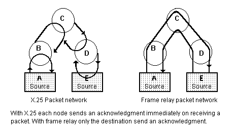 With X.25, each node sends an
acknowledgment immediately on receiving a packet. With frame relay, the final destination
terminal sends acknowledgment, making this technique faster. To support frame relay, the
intermediate addresses must be preserved, and the ability to send an acknowledgment to the
correct sending device must be built into the intermediate nodes of the system.
Cell
Relay
 Asynchronous Transfer Mode (ATM)
Asynchronous Transfer Mode (ATM) is an
International Telecommunication Union- Telecommunication Standardization Sector (ITU-T)
standard for cell relay wherein information for multiple service types, such as voice,
video, or data, is conveyed in small, fixed-size cells. ATM networks are connection
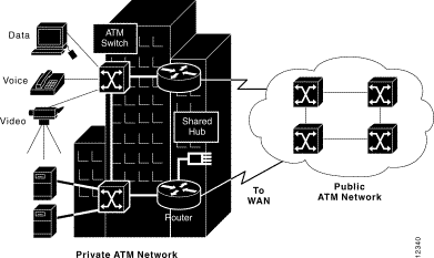
oriented. This chapter provides summaries of ATM protocols, services, and operation. The
figure below illustrates a private ATM network and a public ATM network carrying voice,
video, and data traffic.
ATM is based on the efforts of the ITU-T Broadband Integrated Services Digital Network (BISDN) standard. It was originally conceived as a high-speed transfer technology for voice, video, and data over public networks. The ATM Forum extended the ITU-T's vision of ATM for use over public and private networks.
ATM is a cell-switching and multiplexing technology that combines the benefits of circuit switching (guaranteed capacity and constant transmission delay) with those of packet switching (flexibility and efficiency for intermittent traffic). It provides scalable bandwidth from a few megabits per second (Mbps) to many gigabits per second (Gbps). Because of its asynchronous nature, ATM is more efficient than synchronous technologies, such as time-division multiplexing (TDM).
With TDM, each user is assigned to a time slot, and no other station can send in that time slot. If a station has a lot of data to send, it can send only when its time slot comes up, even if all other time slots are empty. If, however, a station has nothing to transmit when its time slot comes up, the time slot is sent empty and is wasted. Because ATM is asynchronous, time slots are available on demand with information identifying the source of the transmission contained in the header of each ATM cell.
ATM transfers information in fixed-size units called cells. Each cell consists of 53 octets, or bytes. The first 5 bytes contain cell-header information, and the remaining 48 contain the "payload" (user information). Small fixed-length cells are well suited to transferring voice and video traffic because such traffic is intolerant of delays that result from having to wait for a large data packet to download, among other things. The figure below illustrates the basic format of an ATM cell.

An ATM network consists of a set of ATM switches interconnected by point-to-point ATM links or interfaces. ATM switches support two primary types of interfaces: UNI and NNI. The UNI connects ATM end systems (such as hosts and routers) to an ATM switch. The NNI connects two ATM switches.
Depending on whether the switch is owned and located at the customer's premises or publicly owned and operated by the telephone company, UNI and NNI can be further subdivided into public and private UNIs and NNIs. A private UNI connects an ATM endpoint and a private ATM switch. Its public counterpart connects an ATM endpoint or private switch to a public switch. A private NNI connects two ATM switches within the same private organization. A public one connects two ATM switches within the same public organization.