06.621 Data Communications and Networks 2
Week 5 – Line Utilisation Strategies
Learning Outcomes
By the end of this session the student should be able to evaluate the function and
utilisation of different hardware to make a network run more efficiently, faster and more
securely. The hardware considered will include multiplexers, multiport modems,
concentrators, and terminal servers.
Introduction
In the early days of remote terminal access, a
remote terminal used a pair of modems to communicate across a public telephone line.
Initially a pair of modems enabled a single remote terminal to access a mainframe
computer. The introduction of multiplexers allowed several terminals to share a single
telephone line. More recently the terminal servers provide an alternate means of
connecting multiple terminals to a host computer using a single telephone line.
Terminal Connections
When data is sent
over a network with many terminal locations, some arrangement must be made to enable the
different terminals to communicate with one another. Early communication networks used
permanent connections between the host computer and the each terminal. When the number of
terminals exceeds two or three, however, this system gets increasingly expensive.
For local terminals, the
connection to the host is from the RS-232 port of the terminal through to either a
front end processor on the host or a board that accept multiple RS-232 lines into the
host.
Remote Terminals have a more
complex arrangement and rely on the use of modems to send digital data from the
host computer and the terminal across a voice grade communication line.
 The diagram shows the basic
hardware configuration for a data communication network, starting at the host computer end
and working out to the remote end. Other hardware not shown in the diagram, include
multiplexers, intelligent controllers, protocol converters and line adaptors.
The Host Mainframe Computer
The diagram shows the basic
hardware configuration for a data communication network, starting at the host computer end
and working out to the remote end. Other hardware not shown in the diagram, include
multiplexers, intelligent controllers, protocol converters and line adaptors.
The Host Mainframe Computer
The host mainframe computer generally is considered to be the central
computer or central processing system. In distributed processing, several host computers
may be tied together by the data communication network. Although the host computer is not
truly part of the network, it performs many network functions because these functions may
be shared by the host computer and front end processor.
Front End Processor (FEP)
The front end
processor can take two forms. The first is a non-programmable, hardwired.
communication control unit designed by the manufacturer to adapt specific line and
terminal characteristics to the computer. The second is a front end processor that is
programmable and can handle some or all communication input/output activity as well as
perform some processing. The general rend today is to remove every data communication task
that you can from the host computer and move it out further into the network.
The basic components of the front
end processor are as follows:
Channel Interface is the hardware interface that permits the communication
processor to connect directly to the standard channel of the host computer.
Software is the highly specialised set of stored programs that define the
specific architecture/protocols of the front end. The software determines which standard
protocol should be used for the front end. Some of this software is built into firmware,
that is the programs are coded into the circuit chips instead of being programmed logic.
Line interface units (also called ports) are hardware devices used to link the
communication processor with the modems that terminate each communication circuit.
The functions of the front end
processor include:
Communication line control.
Polling/selecting of individual
terminals, intelligent terminal controllers, or network nodes. Polling is asking
each terminal if it has a message to send, and selecting is asking each terminal
whether it is in a condition to receive a message.
Automatic answering,
acknowledgment, and dialling for outgoing calls.
Port selection, which allows
several circuits to share a single port. The port is the plug or connection point
where individual lines enter the front end processor.
Ability to address messages to
specific terminals
Circuit switching, which allows one
incoming circuit to be switched directly to another when it is available.
Automatic routing of messages to a
backup terminal when a specific terminal or circuit is out of order.
Addition or deletion of
communication line control codes. Line control codes are the grammar of data
communication, such as the END OF BLOCK, BEGINNING OF BLOCK and the START OF MESSAGE.,
must be deleted before the message is passed to the host computer and must be added before
the message id passed to the communication circuits.
Protocol/Code Conversion - code
conversion, that is, the software or hardware conversion from one code format to another
such as ASCII to EBCDIC. Conversion from one protocol to another, which allows different
machines to talk to each other if they all use different protocols such as HDLC, SDLC,and
X.25.
Assembly of Characters/Messages -
Assembly and disassembly of bits into characters. Bits are transmitted in serial fashion
on a communication circuit. The FEP assembles these into parallel characters for the host
computer to accept.
Assembly/disassembly to handle
synchronous or asynchronous modes of transmission.
Handling of transmission speed
differences where different communication circuits transmit at different bit per second
rates.
Data and Message Editing - Control
editing, which consists of adding items to a message, rerouting messages, rearranging data
for further transmission, or looking for nonexistent addresses.
Message compression or compaction,
which is a methodology for transmitting meaningful data messages but through the
transmission of fewer data bits.
Signalling of abnormal occurrences
to the host computer.
Assignment of consecutive serial
numbers to each message and possibly, time and date stamping of each individual message.
Message Queuing/Buffering - Slowing
the flow of messages when the host computer or the remote terminal station (node) is
overburdened by traffic.
Queuing messages into distinct input queues and output queues between the FEP and the host
computer or between the FEP and the outgoing communication circuits.
Giving different priorities to
different communication circuits or automatically assigning priorities to various types of
messages to speed the throughput of various message types.
Handling of time-out facility, such
as when a specific terminal station does not respond or when a circuit ceases to respond.
Error Control - Error detection and
automatic transmission for parity checks on message blocks (CRC check and others).
Forward error correction techniques
to reduce errors flowing through the communication circuits.
Message Recording - Logging all
inbound and outbound messages on magnetic tape for a historical transaction trail.
Logging the most recent 20 minutes on a magnetic disk for immediate restart and recovery
purposes.
Other Functions
Multiplexing
Automatic switchover to a backup
host computer in the event of a primary host failure.
Circuit concentration where a
number of low speed circuits might interface to one higher speed communication circuit.
Performance of some functions of
the Packet Assembly/Disassembly (PAD), if the front end processor is also serving as a
switching node in a packet switching network.
Network Control Networks can
operate in a central control mode or an interrupt mode. The central control
mode involves centralised polling of each station device (terminal or node) on the
network. Polling is the process of individually giving each of the terminals
permission to send data one at a time.
The interrupt philosophy implies
that when a terminal sends data, the incoming data stream interrupts the hosts computer
and the host stops processing so it can handle the incoming data. Because this mode is
wasteful of processing capacity it is not generally used on host computers, except for
some microcomputer systems that have very few terminals on local area networks.
Modems
Another essential piece of equipment is the modem at the host end of the network. A modem
is the first piece of equipment encountered at the remote end. Modem is an acronym for
MOdulator/DEModulator. A modem takes digital electrical pulses received from a computer,
terminal, or microcomputer and converts them into a continuous analog signal that is
acceptable for transmission over a voice grade circuit. Until recently all of these
devices were analog modems, because the signal was sent over an analog voice grade
communications circuit. The introduction of all-digital circuits required digital modems.
Multiport Modems
Multiport modem cards are
devices that are designed to accomodate modems (56k), ISDN, and other analog calls through
a single dial-up number.
Cards are available in 4 and 8 card models and come equipped with on-board processors that
offload communications tasks from the server to improve overall performance.
Multiplexers
The diagram showing the basic
hardware needed for communication networking did not include several additional hardware
devices that are used to help the network to run more efficiently and faster, to be more
secure and easier to use, to interconnect to other networks and so forth. The additional
equipment includes multiplexers, intelligent controllers, protocol converters, hardware
encryption devices and line adaptors.
To multiplex is to place
two or more simultaneous transmissions on a single communication circuit. An important
aspect of multiplexing is transparency. Transparent means that the hardware multiplexer
box does not interrupt the flow of data. Neither the computer, nor the modem, nor the
terminal/microcomputer using the modem knows the multiplexer is being used regardless of
whether the transmission is on a leased or dial-up circuit. When a circuit is multiplexed
at one end and demultiplexed at the other, each users terminal thinks that it has its own
connection to the host mainframe computer. Multiplexing is usually done in multiples of 4,
8, 16 or 32 simultaneous transmissions over a single communications circuit. Multiplexers
can be separated into major categories such as frequency division multiplexers (FDM), time
division multiplexers (TDM), and statistical time division multiplexers (STDM).
Frequency Division Multiplexing (FDM)
Frequency division multiplexing can be described as having a stack of four or more modems
that operate at different frequencies so their signals can travel down a single
communication circuit. Another way of looking at FDM is to think of a group of singers.
There may be a combination of a bass, an alto, a tenor and a soprano. What you hear is a
combination of the four singing, but sometimes you can identify clearly one or more of the
individual singers.
With FDM, the frequency division
multiplexer and the modem are usually combined into the single piece of hardware. In FDM,
the frequency divisor multiplexer uses the 3,000 cycles of available bandwidth in a voice
grade circuit, dividing it into multiple subchannels.
 The multiplexer shown, is
subdividing the bandwidth of the voice grade circuit into four pairs of frequencies
allowing four simultaneous transmissions of 0s and 1s. The guardbands are the unused
portions of bandwidth that separate each pair of frequencies from others.
Time Division Multiplexing (TDM)
The multiplexer shown, is
subdividing the bandwidth of the voice grade circuit into four pairs of frequencies
allowing four simultaneous transmissions of 0s and 1s. The guardbands are the unused
portions of bandwidth that separate each pair of frequencies from others.
Time Division Multiplexing (TDM)
Time division multiplexing is really a type of time slicing or sharing the use of a
communication channel among two or more terminals. Each terminal takes its turn.
 In TDM the multiplexer takes a
character from each transmitting terminal and puts them in a frame . The frames are put
onto a high speed data stream for transmission to the other end of the circuit. With TDM
if four terminals share a 4,800 BPS line, then each terminal can transmit at 1,200 BPS. If
any three terminals are transmitting then the frame will contain a blank bit for that
terminal.
TDM is generally more efficient
than FDM, but it does require separate modems. It easy to expand a TDM from, let us say, 8
to 12 channels. All TDM channels usually originate from one location and all terminate at
another location.
Statistical Time Division Multiplexing
In TDM the multiplexer takes a
character from each transmitting terminal and puts them in a frame . The frames are put
onto a high speed data stream for transmission to the other end of the circuit. With TDM
if four terminals share a 4,800 BPS line, then each terminal can transmit at 1,200 BPS. If
any three terminals are transmitting then the frame will contain a blank bit for that
terminal.
TDM is generally more efficient
than FDM, but it does require separate modems. It easy to expand a TDM from, let us say, 8
to 12 channels. All TDM channels usually originate from one location and all terminate at
another location.
Statistical Time Division Multiplexing
Statistical time division multiplexing allows the connection of more terminals to the
circuit than the capacity of the circuit. In its simplest context, you have 12 terminals
connected to a statistical time division multiplexer and each terminal can transmit at
1,200 BPS, then your total is 14,400 BPS transmitted at a given time. However, if the
STDM/modem/circuit combination has a maximum speed of only 9,600 BPS, there may be a time
when the system is loaded above its capacity.
The technique of statistical time
division multiplexing takes into effect that there is some downtime because not all
terminals transmit the maximum capacity rated for every possible available millisecond.
With this in mind, you start by addressing each character in the frame or message and time
division on a statistical basis.
 For example assume we have a
statistical time division multiplexer that multiplexes individual characters from 12
terminals. In the case the terminal address is picked up in addition to the character and
is inserted into the frame. Now the multiplexer only takes a character when the terminal
has a character to send.
Stat muxes, as they are called,
use software and a microprocessor chip built into the multiplexer. They can support a
number of different devices at different speeds, without the modem having to equal the
combined speeds of all the attached devices. Although STDM can be very efficient, it can
cause time delays. When traffic is very heavy there can be anything from a 1 to a 30
second delay. Some data is held in buffers when too many terminals attempt to communicate
at maximum capacity for too long a period of time.
Concentrators
For example assume we have a
statistical time division multiplexer that multiplexes individual characters from 12
terminals. In the case the terminal address is picked up in addition to the character and
is inserted into the frame. Now the multiplexer only takes a character when the terminal
has a character to send.
Stat muxes, as they are called,
use software and a microprocessor chip built into the multiplexer. They can support a
number of different devices at different speeds, without the modem having to equal the
combined speeds of all the attached devices. Although STDM can be very efficient, it can
cause time delays. When traffic is very heavy there can be anything from a 1 to a 30
second delay. Some data is held in buffers when too many terminals attempt to communicate
at maximum capacity for too long a period of time.
Concentrators
In today's terminology, concentrators are special forms of statistical multiplexers.
Concentrators are used for the same purpose as multiplexers. In fact they originally were
intelligent multiplexers (stat muxes).
The primary use for the
concentrator is to combine circuits because you have 16 low or medium speed circuits that
are concentrated into one or two high speed circuits. For example, you might concentrate
approximately twelve 4800 BPS communication circuits into 56,000 BPS digital communication
circuit. Even though this does not work out exactly (12 x 4800 = 57,600), the statistical
intelligence takes care of the small difference. Like stat muxes, concentrators can buffer
or hold back data. Some concentrators can even switch messages to different communication
circuits.
Terminal Servers
A terminal server is a device that accepts incoming data
calls and routes request for services to the appropriate source. Examples of termial
servers are the Ascend MAX 4000, the U.S. Robotics Total Control Hub, the Shiva LAN Rover,
and the Computone Intelliserver.
Terminal servers generally support incoming analog as well
as ISDN calls. Some terminal servers can support analog calls which are delivered over a
T1 line, called a Digital Supertrunk. A channelized-T1 line provides 24 inbound data
calls, one per DS0 channel. Usually one phone number is assigned for customers to call in
on and software at the Telco's CO switch provides a "hunt-group" which directs
the next call to the first available modem. Each of the 24 lines has a unique phone
number, but 23 of these are only seen by the telco switch. This is a convienience to both
ISPs and customers.
Older terminal servers like the Computone Intelliserver
require discreet phone lines be connected to individual discreet analog modems. This is a
less than satisfactory solution since all those modems take up enormous amounts of space
in an ISP's Network Operations Center.
A terminal server also incorporates a router, which is
responsible for sending requests out to the proper server, and for receiving replies from
servers and sending them back out to the appropriate modem line.
Some newer terminal servers, like the Ascend MAX and the
U.S. Robotics Total Control Hub accept both analog and ISDN calls. They use special
devices which can handle both types of calls. They can do this because an analog phone
call is actually a digital call at every point in the phone network except the local loop
(the wire from your house to the Telco's Central Office (CO) switch. Modem stands for
MOdulator/DEModulator. An Analog signal is modulated to become digital, sent out over the
phone company network, and then demodulated (returned to an analog signal) at the other
end. If the "other end" can handle digital data, then why remodulate the signal
to analog? Why not just deal with it as a digital signal? That's exactly what the new
terminal servers do. They can recognize the difference between an ISDN call and a
digitized analog call by the signaling information sent over the D channel (in the case of
an ISDN call) or the absence of it (in the case of a digitized analog call). Once they
recognize the type of call, they switch it to the appropriate internal circuitry for
decoding and routing.
Terminal servers also handle login authentication. Most use
a RADIUS (Remote Access Dial-In User System) database directly to check that a dial-in
connection has a valid login name and password before they will accept the connection.
Terminal servers are expensive devices, costing anywhere
from $19,000 to $40,000.
Most vendors now refer to their terminal server products as
Access Switches.
Terminal Servers Vs. Multiplexers...
As more companies find themselves replacing outdated
terminals with workstations and PCs LANs, a basic architecture question often arises. Most
trade journals are touting new terminal server equipment as a replacement for traditional
statistical multiplexers. However, they don't analyze the realities of wide area
networking in those articles, so many designers are left with insufficient information on
how to determine the best architecture for a given application.This section will provide
that missing information and a methodology you can use to select the best architecture.
The "traditional" method of connecting remote
users to a central UNIX system is shown in figure one. This is termed a "muxed
system". The system consists of remote terminals connected through a statistical
multiplexer and single communications line to the host computer site. The multiplexer
enables many terminals to share the same line by manipulating the data in transit so that
each user seems to have a direct connection to the computer. Statistical techniques are
built into the multiplexer to optimize the use of that single line. Typical systems serve
four to thirty or more terminal users through one data line to the host system. The
terminals may be "dumb" terminals, PCs emulating terminals, or workstations
emulating terminals. The electrical interface between these devices and the multiplexer is
typically RS-232. Each terminal device is connected to a specific port on the host
computer. This system supports "nailed" remote printers on host computer ports
configured for printers; that is, each remote printer is always tied to the same host
port. The system is relatively high performance, quite bandwidth efficient, simple, and
has the advantage of nailed remote printers. All configuration can be performed from the
host site, and no complex equipment is installed at the remote sites.
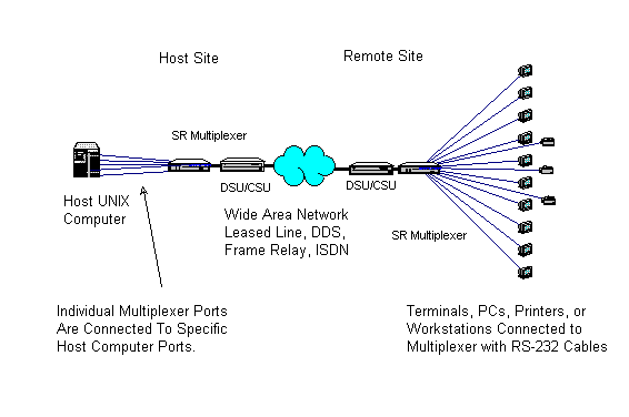
Figure One. Multiplexer System.
An equivalent terminal server system is shown in figure
two. In this architecture, a terminal server instead of a multiplexer is located at the
remote site. The remote site must have a LAN and one or two routers are needed to connect
the remote terminal server to the host site. User terminals (dumb terminals, PCs,
workstations) are connected to the terminal server's RS-232 interfaces. If desired, some
workstations can connect to the host via the routed connection using telnet over the
LAN/WAN. Printers are connected to the terminal server which must use the LPR/LPD protocol
to print from the host computer. Terminal connections are usually dynamic; a given
terminal will connect to various logical TTY ports on the host computer... instead of
always connecting to the same TTY port as in a muxed system. The terminal server
communicates with the host using ethernet and TCP/IP protocols. This system is not as
bandwidth efficient as a muxed system and is more complex. Its main advantage is the use
of a routed connection that may be required for other applications such as a graphics UNIX
X-terminal system. The terminal server can also connect to more than one host computer, so
if a terminal needs to switch between hosts, a terminal server is required.

Figure Two. Terminal Server System.
What are the compromises? What tradeoffs are required and
which ones are optimized? Lets compare the two methods on a point-by-point basis. We will
compare an 8 port system using each method. Equipment common to both systems is ignored
(DSU/CSU, cables)
- 1. Performance.
- With equivalent recurring communications cost (the same data
line between the host and remote sites), Muxed systems will always perform better than
terminal server systems. Muxed systems optimize data line utilization by analyzing the
data with statistical methods and customizing the data throughput on a moment-by-moment
basis. There is very little overhead passed through the communications link. Terminal
Servers package each keystroke (for normal typists) or small group of keystrokes( if you
are blazingly fast typing) into an Ethernet packet. That adds tremendous overhead to the
system. For example, when viewing a menu screen, you press the enter key to make a
selection. The terminal server will send 64 characters to the host system just to transmit
that enter keystroke. That's a 6400% overhead. Obviously, when sending larger blocks of
data such as printing to a remote printer, the overhead goes down; but, it is still quite
substantial. Overhead on a muxed system is quite low. Multiplexers are tuned for a mix of
relatively slow operations such as typing on a keyboard or displaying information on a
screen along with printing on a remote high speed printer. For Performance, Muxed systems
win hands-down.
- 2. Bandwidth Requirements.
- A terminal server architecture will need about five to ten
times the bandwidth of a muxed system for comparable response time performance. That
additional bandwidth is a recurring cost each month. For bandwidth cost, Muxed systems win
by a large factor.
- 3. Equipment Requirements.
- The Muxed system requires only two multiplexers. Terminal
server requirements require a terminal server and a router (possibly two routers). If the
applications is character intensive, a second router may be required to support a
high-speed WAN link. Per Port cost is about the same for both systems.
- 4. System Complexity.
- Terminal server systems are more complex than muxed systems.
Terminal servers require TCP/IP configuration, remote printer LPR/LPD configuration, and
on-going administration to support these configurations as well as port configuration.
Other than the port configuration, there is no additional configuration for a muxed
system. Troubleshooting is much easier on a muxed system. There are no protocol issues
involved in the muxed system. Terminal server systems rely upon routed ethernet and TCP/IP
protocols with many potential points of failure.
- 5. Voice and Data integration.
- Using a muxed system on a 56 Kbps line allows adequate
terminal response when integrated with a channel or two of voice. Routed systems require
at least 56 Kbps bandwidth so any voice added to a routed system will noticeably affect
performance.
Terminal Server Vs. Multiplexer
Comparison
| Characteristic |
Multiplexer |
Terminal Server |
| Equipment Requirements and cost. 8 Remote Ports |
Two Multiplexers
$ 4,200 * |
One Terminal Server, One Router minimum, possibly two.
$ 3,500 - $ 4,500 * |
| Bandwidth Requirements |
LOW (Minimum 19.2Kbps) |
HIGH (Minimum 56 Kbps) for equivalent throughput |
| Response Times (Performance) |
FAST |
SLOW |
| Complexity |
LOW |
HIGH |
| Feasibility of adding voice on 56Kbps line |
POSSIBLE |
NOT ADVISABLE Due to Bandwidth Requirements |
| Host switching |
Not Available |
Available |
| Applications |
Character Mode Applications Well Supported |
Poor Support of Character Mode Applications |
| Life Cycle Cost |
LOWER |
HIGHER |
* Prices are based on DCB multiplexer, router and terminal
server solutions.
Checking the chart above shows that most of design compromises favor the muxed system in
average applications. So why are terminal server systems installed so often? First, they
are trendy. Many people depend on the trade journals that push what their advertisers pay
for, and right now, that is ethernet networking gear. Many networking professionals don't
have the experience to see just how robust and responsive a medium speed data line can be.
Often, those who started in the business within the last few years haven't been exposed to
multiplexed systems and don't understand the concepts.
Terminal server systems are appropriate under some
circumstances. If a routed network is required for some other application such as X-Window
workstations, remote email systems, or other internetworking; then the incremental cost of
a terminal server is relatively low. Another factor would be the need for a user to switch
between several host computers. Terminal servers have this capability which isn't
available on muxed systems. The caveat is still centered around bandwidth and performance.
Terminal server systems require much more bandwidth than muxed systems for equivalent
performance.
Which method is best for your application?
The multiplexer route is normally the most cost effective and highest performing option.
If using routed facilities in common with other applications such as X-windows, the
terminal server may provide adequate performance. If host switching is needed, a terminal
server is required. There is a hybrid method, shown in Figure Three, that works very well
for a mixed system of terminal users that need some LAN type access for email. By putting
the routed LAN traffic on one port of a statistical multiplexer, LAN traffic such as email
is available while maintaining the performance advantage of multiplexing terminal access.
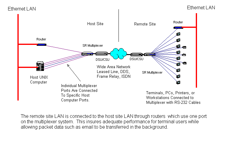
Figure Three. Hybrid Multiplexer/Router System.
Future products will be available that provide the
advantages of both systems. These will use a remote multiplexer in conjunction with a
device that combines multiplexing and terminal services at the host site. Until this class
of products are available, select a method that provides maximum performance with minimum
recurring cost.